
A lot of people start learning about microcontrollers with an Arduino but then want to build their own projects without having to sacrifice their dev board. Or maybe they want to make their own Arduino variant, that is compatible with the IDE. Either way, a common problem is how to burn the bootloader onto the fresh AVR chip. Since AVRs come blank, they need to be set up to be Arduino IDE compatible but to do that you need an AVR programmer (like the USBtinyISP).
This tutorial is an extention of that tutorial. First we'll show how you can make a permanent bootloader-burner by soldering a 28-pin ZIF socket to a proto shield and use the PWM output line of the Arduino to generate a clock. This will let you 'rescue' many chips that have been set to the wrong type of oscillator, or change ones that are set from external oscillator (most Arduino bootloaders) to internal (such as the lilypad)
According to the the ArduinoISP writeup from Arduino.cc, thus does not work with the newest UNO Arduinos. BUT we got it to work just fine, so not sure if the issue was fixed or its a rare error, or what.
Parts
You will need...
- An Arduino
- A proto shield kit
- 28-pin ZIF (zero-insertion force) socket (you can use a plain socket but ZIF is ideal)
- Some wire
- Blank ATmega328P
Assemble
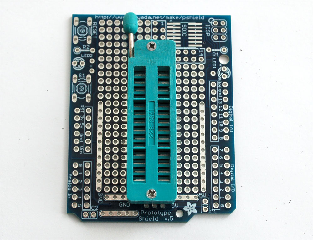
First up, place the ZIF socket on the proto shield like so:

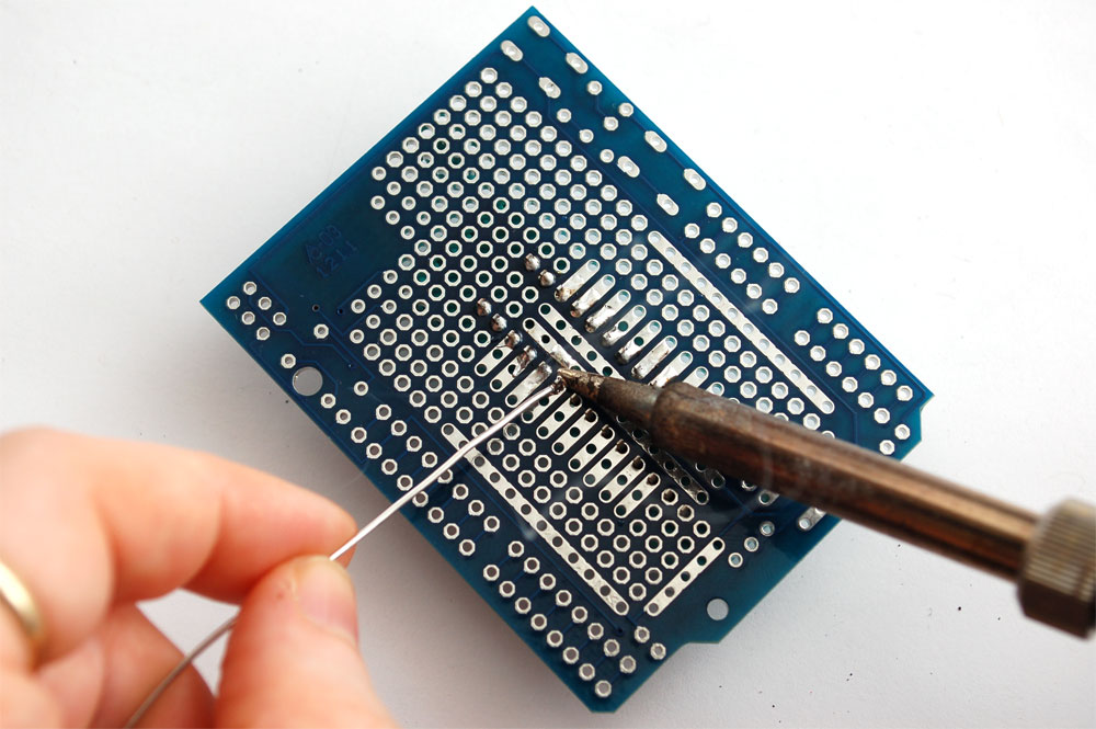
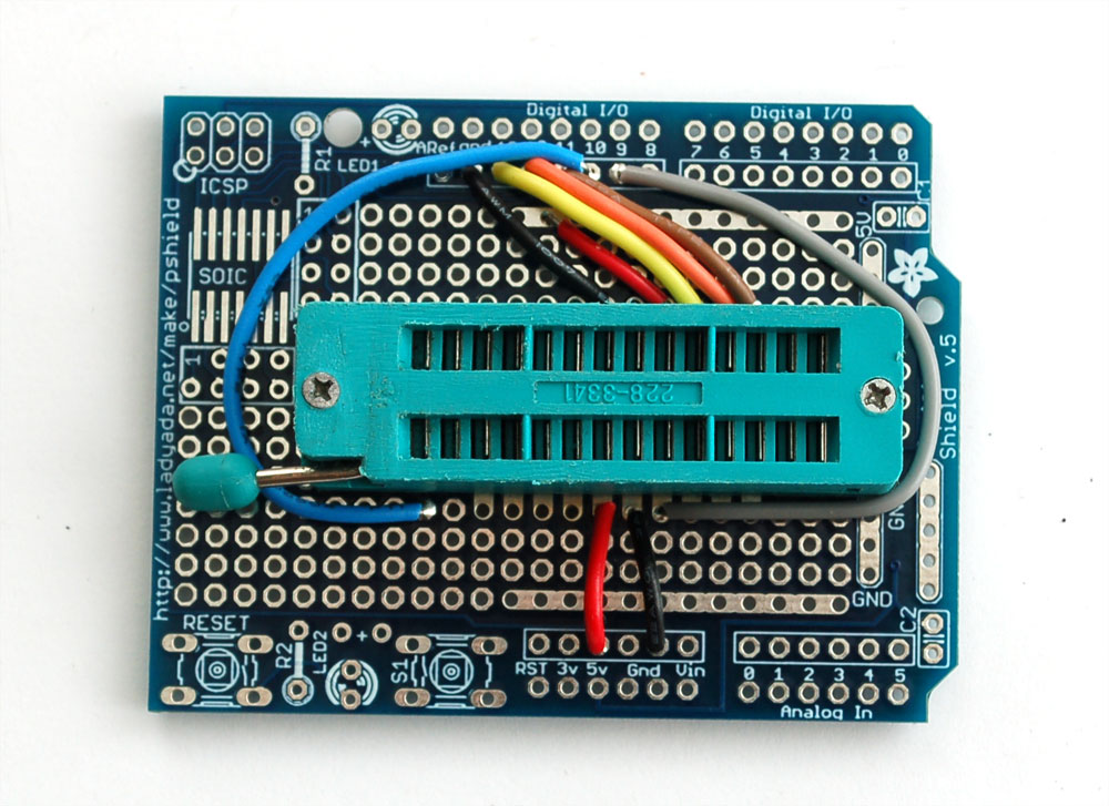
Solder the following wires to the ZIF socket
- Pin 1 to digital 10 - Blue
- Pin 7 to 5V - Red
- Pin 8 to Ground - Black
- Pin 9 to digital 9 - Gray
- Pin 17 to digital 11 - Brown
- Pin 18 to digital 12 - Orange
- Pin 19 to digital 13 - Yellow
- Pin 20 to +5V - Red
- Pin 22 to Ground - Black
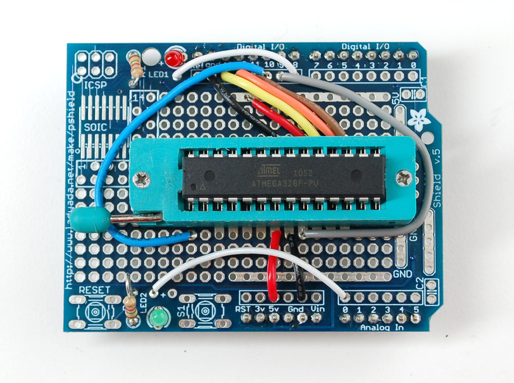
Follow the protoshield tutorial to solder in the Red LED into LED1 position, Green LED into LED2 position. Also solder in the two 1.0K resistors next to the LEDs. We'll use the LEDs as indicators. Then solder a wire from the LED2 breakout (white) to analog 0 and a wire from LED1 breakout (white) to digital 8
Finally, you'll need to solder on the header to allow the shield to be placed on, break the 0.1" male header and place it into the Arduino sockets. Then place the shield above on top to solder it in place
Load the Code
Time to load the sketch! Grab the code from our Github repository and paste it into a new sketch. Then upload it to the Arduino
Plug the shield on top, lift the latch, pop in the chip and then lower the latch. Make sure the chip orientation is like so: so with the lever on the left side you can read the text.
With the USB cable still plugged in (and the same Serial port selected as before) Select Tools->Burn Bootloader->w/Arduino as ISP

The Green LED will be on during the programming, when its done you'll see this message and the LED will turn off

Thats it! Don't forget, you can burn a few different kinds of bootloaders, such as Uno, Duemilanove, Lilypad so depending on your situation you may want to use one over the other.
The parts in this project could be purchase from Adafruit Industries
The parts in this project could be purchase from Adafruit Industries