
by ch00f via ch00ftech
New and Improved
If you've been following my blog, you probably read up on my last attempt at creating a cooler business card. The basic concept was to design a small circuit that when connected to a computer via USB will emulate a mouse and draw out a design. This utilized the ATTiny 85 and VUSB platform which makes writing USB peripherals very easy.
The problem with the original design was that I was controlling the mouse in an open loop manner. I was telling the mouse cursor which way to go, but I had no way to read back the cursor's position. I couldn't account for minor inaccuracies brought about by things like mouse acceleration settings, and the design ended up getting distorted.
After writing that post, I realized that it's possible to configure a mouse to be an absolute input device. An absolute input device is something like a graphics tablet where the device selects precisely where the mouse cursor should go.
Firmware
Most major operating systems will include drivers for so called "generic" human interface devices. This way you never get stuck with a "press any key to install keyboard driver" when you plug in a keyboard. The OS has the driver built in for most basic functions.
These basic functions are defined by the USB spec and cover common things like mouse and keyboard as well as less common peripherals like USB audio and MIDI devices. What I didn't know last time was that they also cover absolute input devices.
This is all specified by the USB device descriptor. A device descriptor is just a series of bytes that are sent to the host machine when a USB device is connected. This includes information such as the device type (mouse, keyboard, etc) as well as info like the manufacturer (USB-licensed manufacturers need to pay for their specific manufacturer IDs. My card just "borrows" one from Logitech).
I don't know anything about the physical aspects of sending a device descriptor, but fortunately, the VUSB firmware that I based my card on handles all of that and only requires that I specify a descriptor array. If you're interested in how this works, I recommend reading their code/documentation.
USB descriptors are literally just a series of bytes, so you need to put them in a very specific order for it to work. I'm not going to go into a whole lot of detail, but I will show you the descriptors I used:
0x05, 0x01,                    // USAGE_PAGE (Generic Desktop)
0x09, 0x02,                    // USAGE (Mouse)
0xa1, 0x01,                    // COLLECTION (Application)
0x09, 0x01,                    //   USAGE (Pointer)
0xa1, 0x00,                    //   COLLECTION (Physical)
0x05, 0x09,                    //     USAGE_PAGE (Button)
0x19, 0x01,                    //     USAGE_MINIMUM (Button 1)
0x29, 0x03,                    //     USAGE_MAXIMUM (Button 3)
0x15, 0x00,                    //     LOGICAL_MINIMUM (0)
0x25, 0x01,                    //     LOGICAL_MAXIMUM (1)
0x95, 0x03,                    //     REPORT_COUNT (3)
0x75, 0x01,                    //     REPORT_SIZE (1)
0x81, 0x02,                    //     INPUT (Data,Var,Abs)
0x95, 0x01,                    //     REPORT_COUNT (1)
0x75, 0x05,                    //     REPORT_SIZE (5)
0x81, 0x03,                    //     INPUT (Cnst,Var,Abs)
0x05, 0x01,                    //     USAGE_PAGE (Generic Desktop)
0x09, 0x30,                    //     USAGE (X)
0x09, 0x31,                    //     USAGE (Y)
0x35, 0x00,                    //     PHYSICAL_MINIMUM (0)
0x46, 0x9d, 0x0b,              //     PHYSICAL_MAXIMUM (2973)
0x15, 0x00,                    //     LOGICAL_MINIMUM (0)
0x26, 0x9d, 0x0b,              //     LOGICAL_MAXIMUM (2973)
0x65, 0x11,                    //     UNIT (SI Lin:Distance)
0x55, 0x0e,                    //     UNIT_EXPONENT (-2)
0x75, 0x10,                    //     REPORT_SIZE (16)
0x95, 0x02,                    //     REPORT_COUNT (2)
0x81, 0x02,                    //     INPUT (Data,Var,Abs)
0xc0,                          //   END_COLLECTION
0xc0                           // END_COLLECTION
The key to this whole operation is where it says INPUT (Data, Var, Abs). Those two bytes (0x81, 0x02) specify that this will be an absolute input device. Of course, reporting absolute position is very different from reporting relative movement.
For starters, when a normal mouse sends information to the host machine, it only needs to send how far the mouse has moved since the last update. This can easily be reported in a single signed byte as it updates very frequently, so distances are short.
Mapping the absolute position of the mouse however requires a lot more data if it's going to provide enough resolution for normal tasks. This is why the "REPORT_SIZE" is set to 0x10. This specifies that each report will be 16 bits in length.
With this configuration, the cursor's location will be specified with two 16 bit numbers. The size of the coordinate plane on which the cursor's location is specified is determined by the "LOGICAL_MAXIMUM" AND "LOGICAL_MINIMUM" values. The larger these numbers, the finer control you have over the mouse cursor. The numbers I used were mostly arbitrary. As long as they're larger than a typical monitor's resolution, you should be good.
One thing I noticed while playing around is that the coordinate plane actually overscans the display. This means that the cursor can actually be told to go beyond the edge of the monitor. I'm not exactly sure why this is the case, and I don't think it's even consistent between displays and operating systems. In my case, the coordinate system overscanned the edge of the display by about 300 units in every direction.
Taking that into account, the coordinate plane looked something like this:
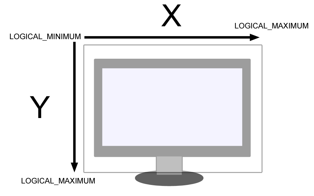
The good news is that as long as my design is relatively small and centered in the coordinate plane, it'll make it onto the usable portion of the plane. What's also convenient is that these coordinate planes scale to the size of the screen, so it should work on anything from a netbook to a 30" monitor.
Artwork
To generate my design, I wrote a quick and dirty Python script that lets me click on an image and record the coordinates of my clicks. I designed the card's firmware so that two clicks at the same exact coordinates causes the firmware to toggle the status of the left click button. This way I just needed to double click at the beginning and end of every line I wanted to draw.
The script also split up each 16 bit coordinate into two 8 bit bytes because the AVR has an 8 bit processor and is only able to store single byte blocks in its program memory. Furthermore, you can only index 256 bytes in a single program memory array, so I had to split my design into two separate stacks of arrays that were each less than 256 bytes long.
This left me with 8 arrays:
- Low byte of X for first half of design
- High byte of X for first half of design
- Low byte of Y for first half of design
- High byte of Y for first half of design
- Low byte of X for second half of design
- High byte of X for second half of design
- Low byte of Y for second half of design
- High byte of Y for second half of design
Edit: I just remembered that AVR-GCC supports multi-dimensional program space arrays. This means that I could have just defined a 256x8 array rather than 8 separate arrays. This is the solution I used to store color mixtures in my DJ Jacket. In the end, the assembled code looks more or less the same, but I could have cleaned up my C code a bit and made this solution more scalable for larger designs.
Once compiled, the code was only slightly larger than 4 kbytes. The ATTiny 85 has 8K of memory, so I could actually make a much more sophisticated design in the future.
This process of clicking can get pretty exhausting, so I was prone to make mistakes. To help with this, I wrote another Python script that converts my mouse clicks back into an image, so I can make adjustments without having to actually flash the business card. I'm sure a more capable coder could write a script to generate this data automatically, but I'm a hardware guy, so...
Hardware
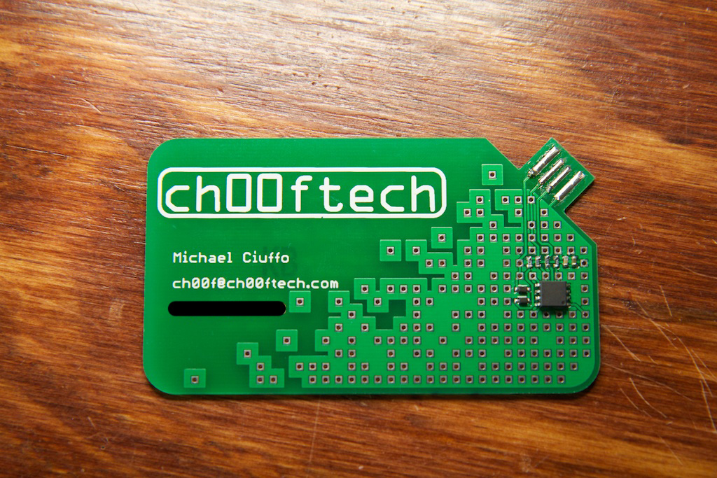
You might have noticed that I borrowed a lot of this design from Frank Zhao. He came up with the idea of obfuscating the programmer pins inside the design of the card. Six of the many exposed vias on the board connect to the six pins of the AVR programming header. The other hundred or so don't do anything at all.
Placing those vias was a blast.
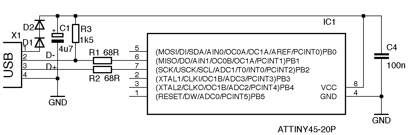
The card was programmed with this small helper circuit:

The device cannot be programmed while it's connected to USB, so the + and - leads let me power the board using an external power supply during programming. These supply leads bypassed the two diode drops coming from the 5V rail (see schematic below), so as long as I kept the external supply voltage high enough, I could actually keep it connected while I plugged the device into the USB port. The diodes wouldn't conduct unless their forward voltage was greater than their potential drop.
The USB connector was taken from SparkFun Connectors Eagle library. The PCB itself wasn't thick enough to seat the card properly, so I added some solder to the pins to thicken it up a bit. This still wasn't quite enough for some USB ports, so maybe next time I'll see about ordering thicker PCB.
Also, the dongle doesn't stick out far enough for some USB hubs, so in the next version, I'll make it longer.
I was surprised to find that the ATTin85 only comes in the wide version of SOIC-8 on Digikey. This is wider than my standard footprint, and I didn't realize until I had already received the PCBs. Fortunately, I got it to work with some creative soldering:
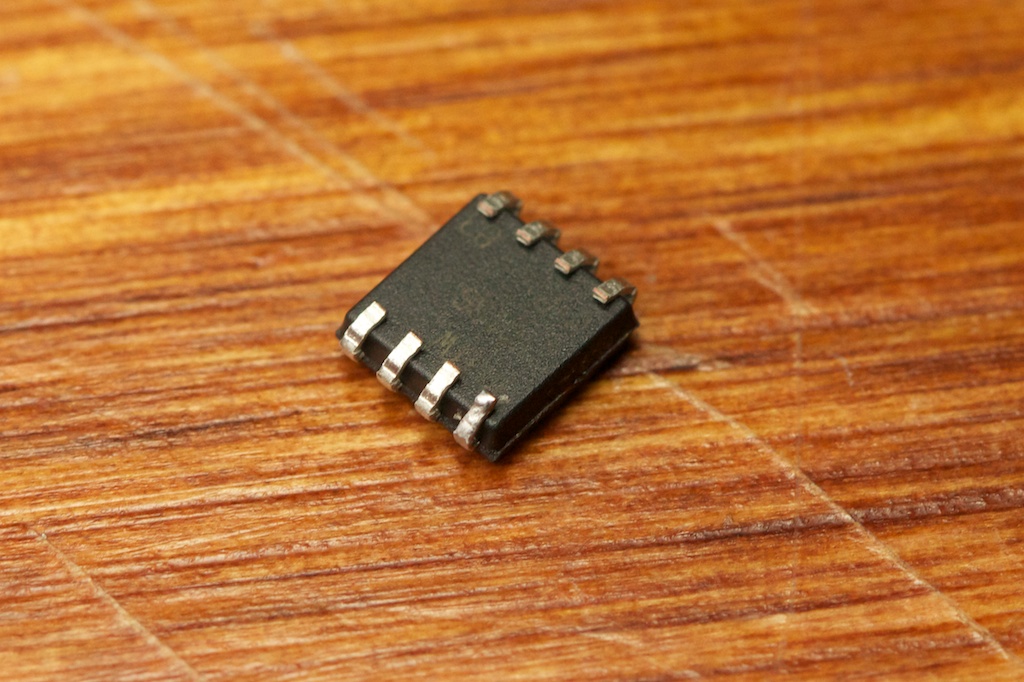

I fixed the footprint anyway for the next version. Fortunately, I didn't have to rearrange anything else to make room.
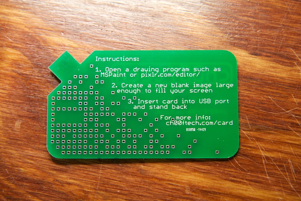
I also included a simple set of instructions on the back of the board. For most setups, the card should work on the first try, but I also included a URL to a small page that offers some troubleshooting tips as well reassurance that this thing won't immediately upload a virus as soon as it's connected.
Performance
As you can see in the video above, the card does more or less exactly what it's supposed to. I have also tested the firmware on OSX, but the USB port of my Mac (that's actually running OSX) is shaped so that the card itself won't fit right.
I don't anticipate it working immediately for everyone, but I figure that it'll still be a fun thing for the recipient to figure out. Besides, all of the important info is printed right on the card, so if nothing else, it's a neat looking card!
Project files can be found here: Business Card v2.0


