
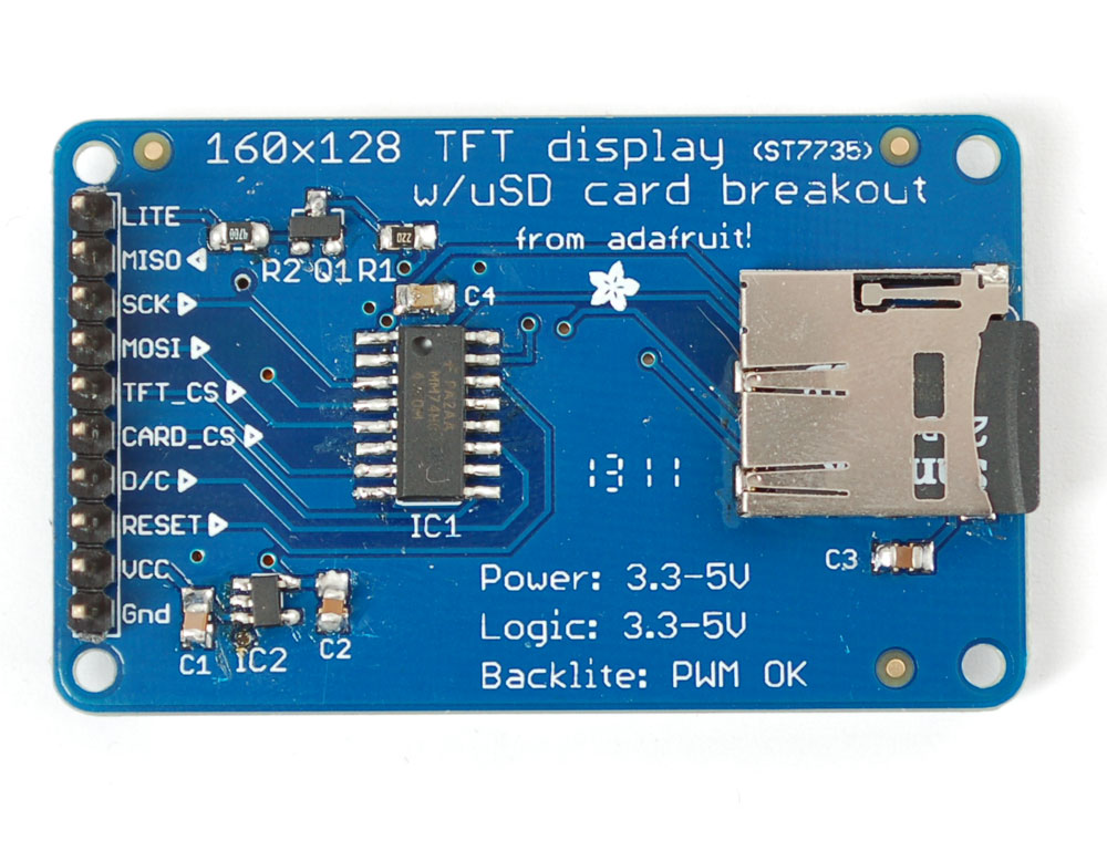
This tutorial from Adafruit is for a 1.8" diagonal TFT display & microSD breakout board. This breakout is the best way to add a small, colorful and bright display to any project. Since the display uses 4-wire SPI to communicate and has its own pixel-addressable frame buffer, it can be used with every kind of microcontroller. Even a very small one with low memory and few pins available!
The 1.8" display has 128x160 color pixels. Unlike the low cost "Nokia 6110" and similar LCD displays, which are CSTN type and thus have poor color and slow refresh, this display is a true TFT! The TFT driver (ST7735R) can display full 18-bit color (262,144 shades!). And the LCD will always come with the same driver chip so there's no worries that your code will not work from one to the other.
The breakout has the TFT soldered on (it uses a delicate flex-circuit connector) as well as a ultra-low-dropout 3.3V regulator and a 3/5V level shifter so you can use it with 3.3V or 5V power and logic. Adafruit board also had a little space to placed a microSD card holder so you can easily load full color bitmaps from a FAT16/FAT32 formatted microSD card.
You can pick up one of these displays in the Adafruit shop!
Flexible wiring
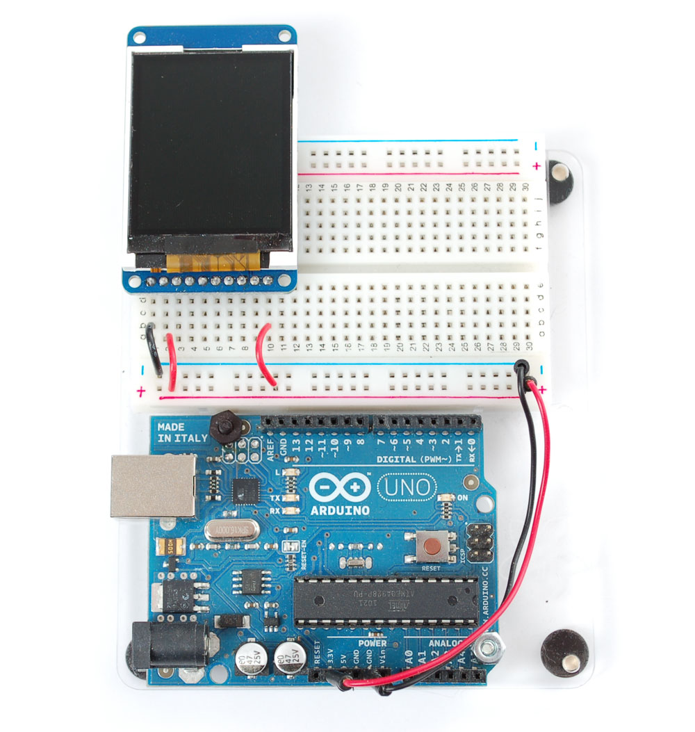
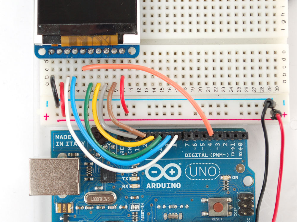
There are two ways to wire up these displays - one is a more flexible method (you can use any pins on the Arduino) and the other is much faster (4-8x faster, but you are required to use the hardware SPI pins) We will begin by showing how to use the more flexible method.

You can use any 4 or 5 pins for this method. We'll show using pins 4, 5, 6, 7, and 8 and once you have it working, you can change those pins around in the wiring and in the sketch.
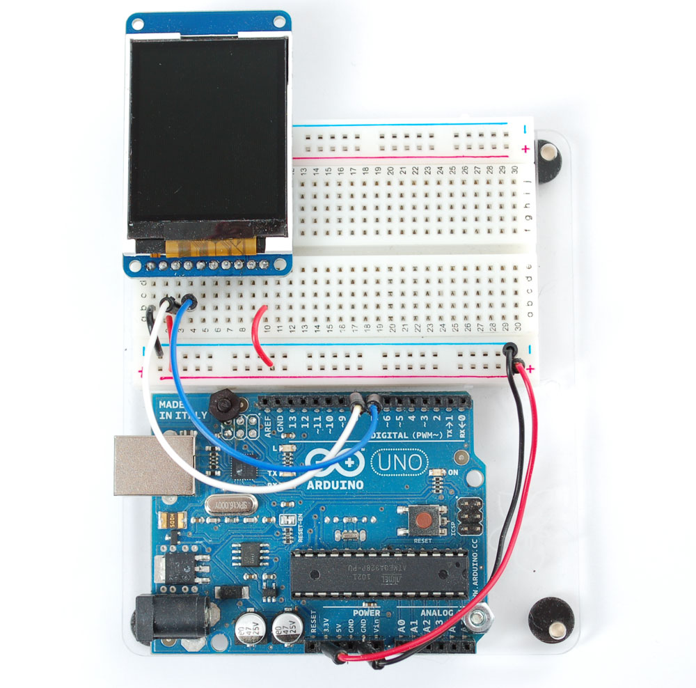
Start by wiring the power pins.

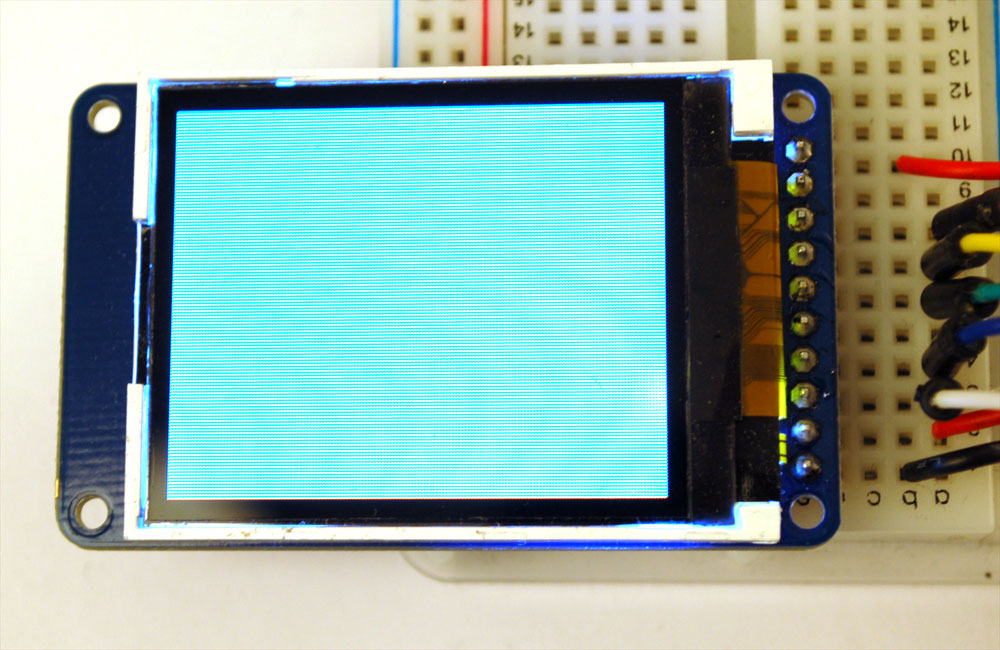
Connect the leftmost pin to Ground and the next pin to +5V. Connect the rightmost pin (backlight) to 5V as well. If you plug in the Arduino you should see the backlight turn on.

Next connect the RESET (TFT reset pin) and D/C (TFT data/command selection pin).

The RESET pin (3rd from the left) connects to Arduino pin 8. The D/C pin (4th from the left) connectso to pin 7
Finally connect the remaining digital pins, TFT_CS (TFT chip select), MOSI (data sent to TFT) and SCK (clock sent to TFT).

Note that you need to skip a pin on the TFT after D/C - the next wire is from TFT_CS which is 6th from the left. This goes to digital pin6. MOSI (7th from the left) connects to digital pin 5 and finally SCK (8th from the left) connects to digital pin 4
That's it! If you want to change the wiring, you can use any pins but don't forget to change the top of the sketch to match!
//You can use any (4 or) 5 pins #define sclk 4 #define mosi 5
#define cs 6 #define dc 7 #define rst 8
// you can also connect this to the Arduino reset
Test Display
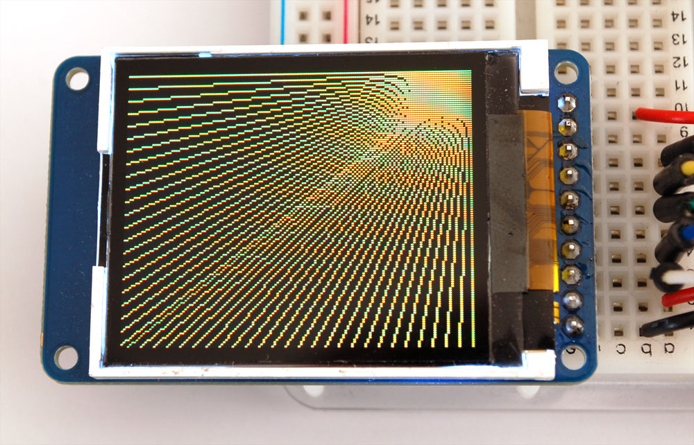
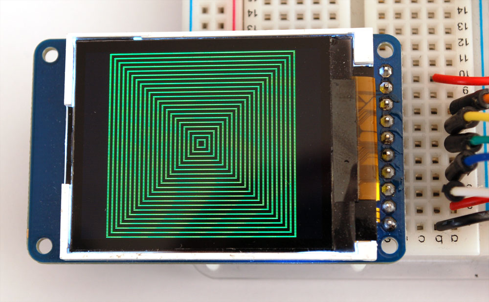
Once you have the display wired up, its time to test your wiring by uploading the example code we have written. Adafruit suggest using an Arduino to test.
Download Adafruit's Arduino library (see bottom of page) from github by clicking on Download in the top right corner. Uncompress the folder and rename it ST7735 - inside the folder you should see the st7735.cpp and st7735.h files. Install the ST7735 library foler by placing it in your arduinosketchfolder/libraries folder. You may have to create the libraries subfolder if this is your first library.You can read more about installing libraries in this tutorial
Restart the Arduino IDE. You should now be able to select File > Examples > ST7735 > graphicstest sketch. Upload the sketch to your Arduino wired as above.

Once uploaded, the Arduino should perform all the test display procedures! If you're not seeing anything - first check if you have the backlight on, if the backlight is not lit something is wrong with the power/backlight wiring. If the backlight is lit but you see nothing on the display make sure you're using our suggested wiring
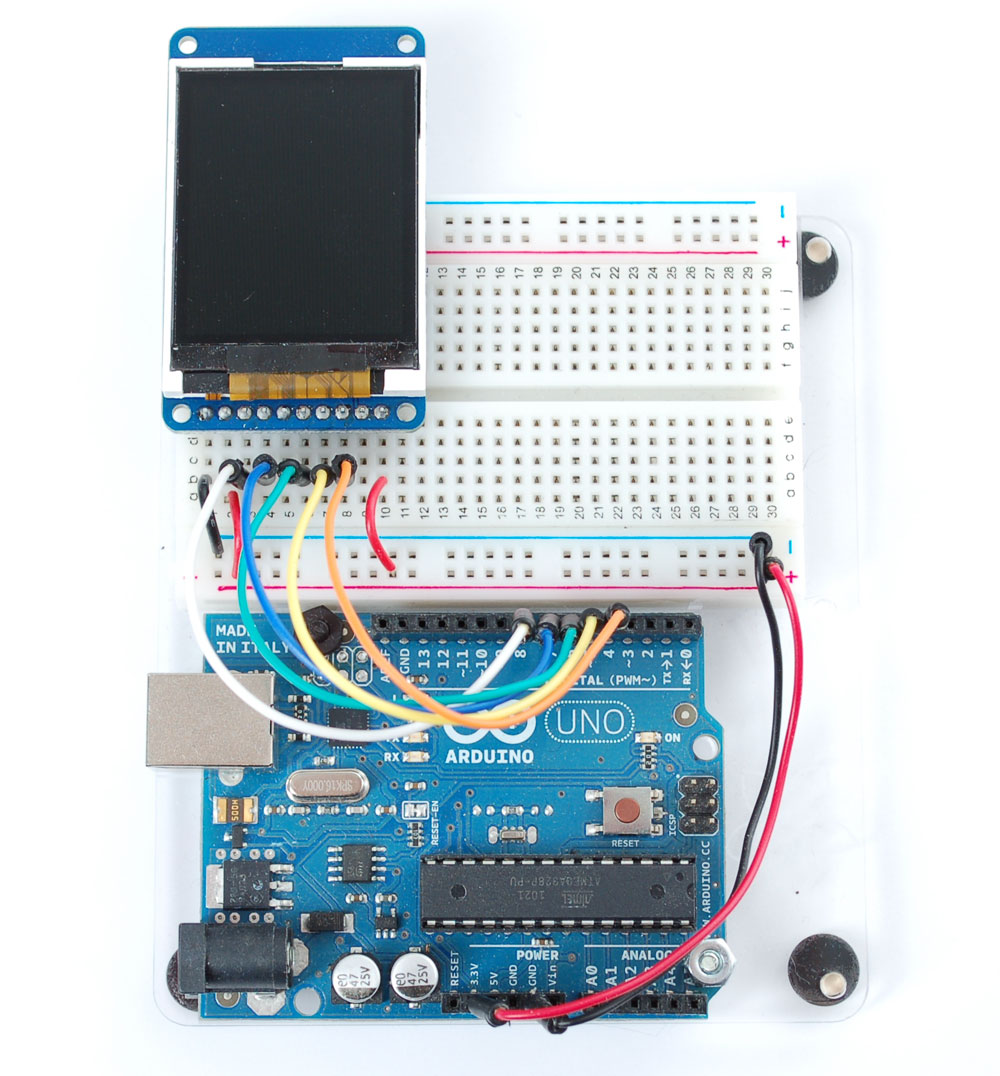
High Speed SPI-Wiring
If you want to connect to the display and have high-speed data transfer (4-8x faster) you'll have to use the hardware SPI system. This is optimized to be faster than the flexible wiring method (because its built into the hardware of the chip) but you are required to use the hardware SPI pins!
On Atmega 328/168/8 type Arduinos ('classic' type) the hardware SPI pins are 11 (MOSI), 13 (SCK) and 10 (CS). For Megas it is 51(MOSI), 52 (SCK), and 53 (CS). The CS pin can be a different pin but if you use any other pin you must still have the hardware SPI CS pin (10 or 53) as an output!
We will also change the TFT_CS pin to be pin 10 and D/C to be pin 9 (you can change these two later but pin 10 must always be an output for hardware SPI to work)
Wiring Diagram
Select the File > Examples > ST7735 > graphicstest_highspeed sketch. Upload the sketch to your Arduino wired as above.
In the sketch we changed the pin definitions
//#define sclk 13
// for MEGAs use pin 52
//#define mosi 11
// for MEGAs use pin 51 #define cs 10
// for MEGAs you probably want this to be pin 53 #define dc 9 #define rst 8
// you can also connect this to the Arduino reset
To use the hardware SPI, we commented out this line
// Option 1: use any pins but a little slower
// ST7735 tft = ST7735(cs, dc, mosi, sclk, rst);
and uncommented this line:
// Option 2: must use the hardware SPI pins
// (for UNO thats sclk = 13 and sid = 11) and pin 10 must be
// an output. This is much faster - also required if you want
// to use the microSD card (see the image drawing example) ST7735 tft = ST7735(cs, dc, rst);
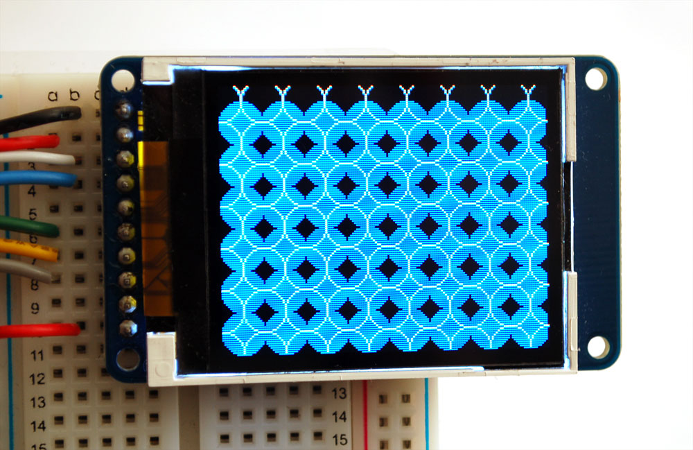
Now when you run the graphics test you'll notice its much faster.
If you want to usethe microSD card and TFT at the same time, you'll need to use the hardware SPI because the SPI pins are shared between the two. See the bitmaps tutorial below for details on how to do this.
Graphics Library
Adafruit has written a full graphics library specifically for this display which will get you up and running quickly. The code is written in C/C++ for Arduino but is easy to port to any microcontroller by rewritting the low level pin access functions. Here are some of the functions we've included in the library
First thing to note is that color is 16-bit (the driver can handle 18-bit but 16-bit is good enough for most applications and fits neatly into a 2-byte word), and that includes Red, Green and Blue in a 16-bit variable. The way the color is packed in is the top 5 bits are red, the middle 6 bits are green and the bottom 5 bits are blue.
For solid colors, we have this handy cheat-sheet. Of course, you can pick any of 65,536 colors but while starting out, this might be helpful
// Color definitions #define BLACK 0x0000 #define BLUE 0x001F #define RED
0xF800 #define GREEN 0x07E0 #define CYAN 0x07FF #define MAGENTA
0xF81F #define YELLOW 0xFFE0 #define WHITE 0xFFFF
Drawing pixels

First up is the most basic pixel pusher. You can call this with two coordinates and a color and it will make a dot:
void drawPixel(uint8_t x, uint8_t y, uint16_t color);
You can also draw lines, with a starting and end point and color
void drawLine(uint8_t x0, uint8_t y0, uint8_t x1, uint8_t y1, uint16_t color);
If your lines are vertical or horizontal, you can call an optimized drawing function that doesn't do all the angular calculations.
void drawVerticalLine(uint8_t x0,uint8_t y0,uint8_t length,uint16_t color);

Next up, rectangles and squares can be drawn and filled using the following procedures. If you want a recangle that has a contrasting outline color, fillRect first, then drawRect over it.
void drawRect(uint8_t x0,uint8_t y0,uint8_t w,uint8_t h,uint16_t color);

Likewise, for circles, you can draw and fill.
void drawCircle(uint8_t x0, uint8_t y0, uint8_t r, uint16_t color);

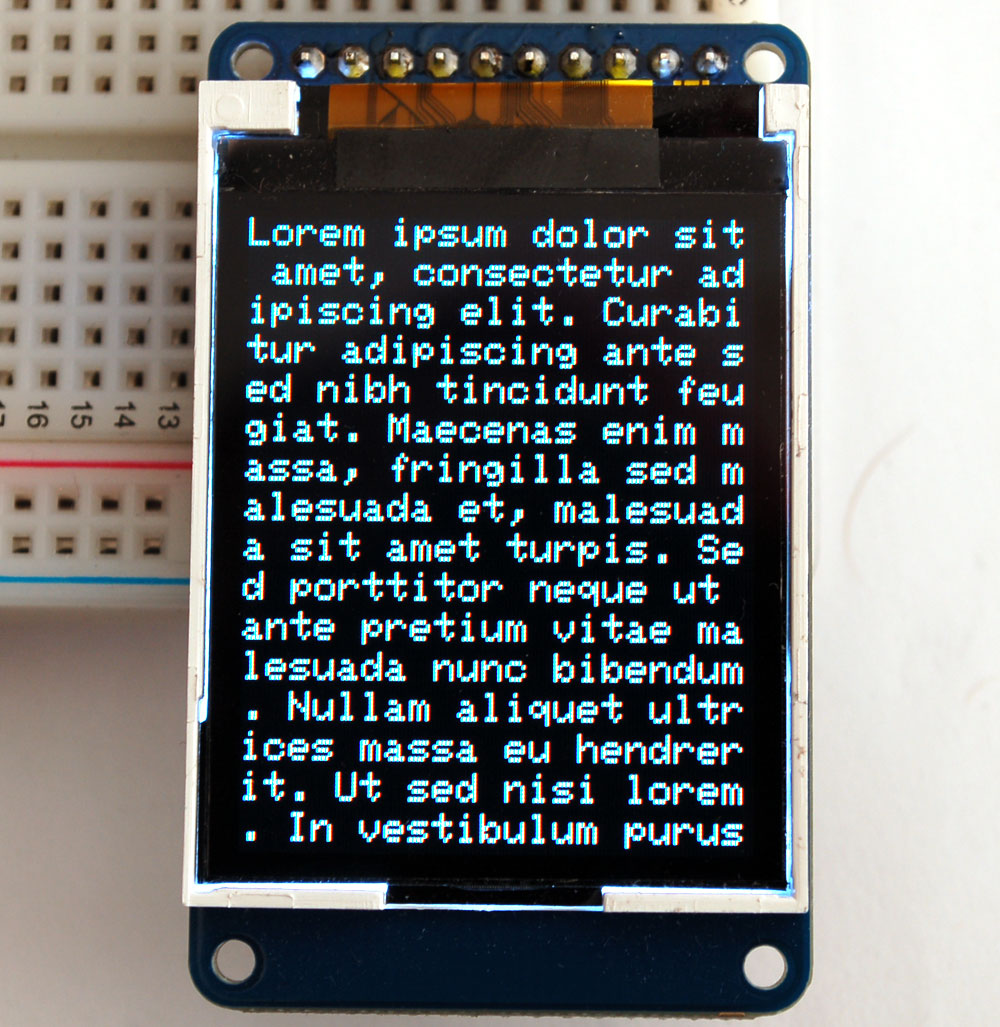
If you need to add some text, there are two basic string drawing procedures. The first is just for a single character. You can place the character anywhere, and with any color. You only have one font to save on space, and its meant to be 5x8 pixels. If you pass size as 1 or if you don't put down a size, that will be what is used. If you need bigger text, the code can scale the font up by passing in a larger size(integer). It's a little blocky but this keeps the flash usage down so we don't need multiple fonts.
void drawChar(uint8_t x, uint8_t y,char c, uint16_t color,uint8_t size);
These primitives should get you started!
Displaying Bitmaps
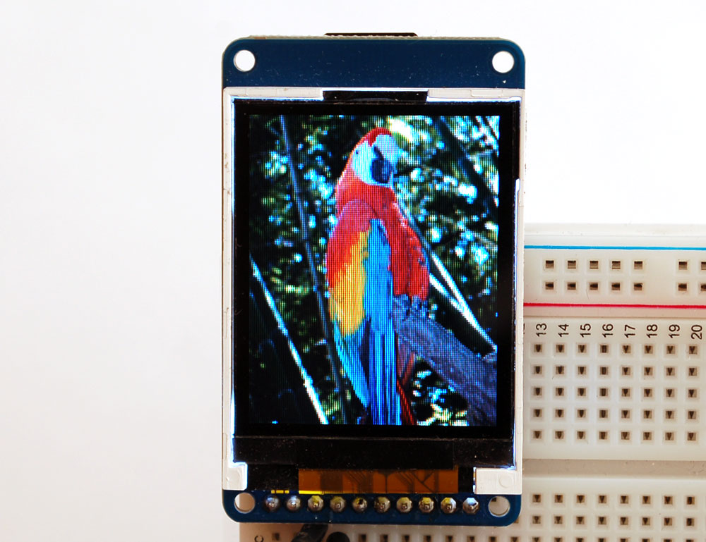
In this example, it shows how to display a 128x160 pixel full color bitmap from a microSD card
Adafruit has an example sketch in the library showing how to display full color bitmap images stored on an SD card. You'll need a microSD card such as this one . You'll also need to download Adafruit's SD library modified to allow faster reads (these changes will hopefully be added to arduino v23) but for now you can download the new library here . Download the library by clicking the Downloads button and uncompressing the folder. Replace the files in your ArduinoIDE/libraries/SD folder (make a backup of course) and restart the IDE.
You'll also need an image. Adafruit suggest starting with this bitmap of a parrot. If you want to later use your own image, use an image editing tool and crop your image to no larger than 160 pixels high and 128 pixels wide. Save it as a 24-bit color BMP file - it must be 24-bit color format to work, even if it was originally a 16-bit color image - becaue of the way BMPs are stored and displayed!
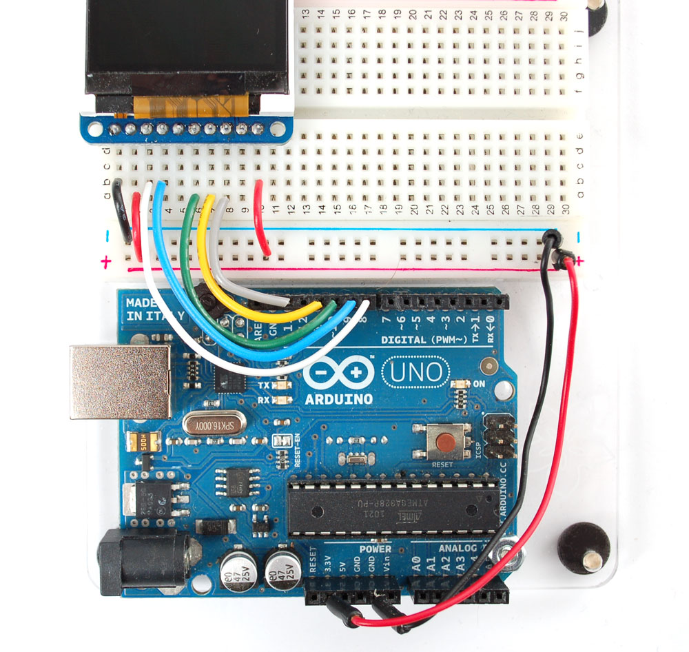
Copy the parrot.bmp to the microSD card and insert it into the back of the breakout board
Wire up the TFT according to the high-speed SPI diagram above. Test that your wiring is correct by uploading the graphics test sketch with the high speed SPI line uncommented and the flexible-low-speed wiring commented.
Once you are sure that the TFT is wired correctly, add the two wires for talking to the SD card. Connect CARD_CS (the unconnected pin in the middle) to digital pin 4 (you can change this later to any pin you want). Connect MISO (second from the right) to the Arduino's hardware SPI MISO pin. For Classic Arduinos, this is pin 12. For Mega's this is pin 50. You can't change the MISO pin, its fixed in the chip hardware.

Now load the bitmap example sketch into the Arduino. It should display the parrot image. If you have any problems, check the serial console for any messages such as not being able to initialize the microSD card or not finding the image.

Downloads
You can download Adafruit's Arduino library with examples from github . To install it, rename the downloaded and uncompressed library toST7735 and place in the sketchfolder/libraries folder. See Adafruit's detailed tutorial for more info.


